

Showing posts with label arduino. Show all posts
Showing posts with label arduino. Show all posts
Sunday, 26 July 2020
Monday, 13 July 2020

Thursday, 25 June 2020

Saturday, 20 June 2020
ultrasonic obstacle avoider car
In this tutorial, I am making a custom obstacle avoiding robot


you can directly print these PCBs from seeedstudio
Seeed Studio Fusion PCB service takes care of the entire fabrication process from PCB manufacturing, parts sourcing, assembly and testing services, so you can be sure that they are getting a quality product. After gauging market interest and verifying a working prototype, Seeed Propagate Service can help you bring the product to market with professional guidance and a strong network of connections.
jumper https://s.click.aliexpress.com/e/_dSRayV5
n20 motors http://s.click.aliexpress.com/e/_dUKwfYM
https://amzn.to/3dkLvk7
ultrasonic module http://s.click.aliexpress.com/e/_d66uQiU
https://amzn.to/2Yl9eMR
n20 motor socket http://s.click.aliexpress.com/e/_dUJpEXq
https://amzn.to/2V2aqCO
n20 wheels http://s.click.aliexpress.com/e/_dXfpot2
https://amzn.to/2Br2rrG
l293d motor driver http://s.click.aliexpress.com/e/_dVSiYYY
https://amzn.to/2Nekggj
castor wheelhttp://s.click.aliexpress.com/e/_dShodxE
https://amzn.to/3eo9znq
Arduino uno https://s.click.aliexpress.com/e/_dUb9laZ
https://amzn.to/2V2wFZ2
Tuesday, 16 June 2020
Tuesday, 5 May 2020
vu meter using arduino
A volume unit (VU) meter or standard volume indicator (SVI) is a device displaying a representation of the signal level in audio equipment.so in this tutorial lets build a VU meter using Arduino.


things needed for this
- Arduino
- led
- aux cable
- jumper wire
- breadboard
circuit diagram
 |
| add an aux to a0 pin |
connections
connect anodes of less to pin 2-13
connect cathodes together and connect to ground
connect aux cable a0 and ground
SOLDERING ON A DOT PCB
arrange in a round shape and solder
Monday, 27 April 2020

Friday, 10 April 2020
electronic chameleon
hey..all of you know about the chameleons.yeay they have a special character to change their colour according to with the environments biologically this is known as mimicry. they use this ability to escape from predators and also to capture their prey.
so in this tutorial, I am replicate that ability electronically with the help of Arduino and colour sensor
please watch the making and working video first
now lets start
HOW ITS WORKS
with the help of tcs230 sensor we can read the reflected colour values of a surface with that data we can control an RGB led
components needed for this project

connections
----------- --------
VCC 5V
GND GND
s0 8
s1 9
s2 12
s3 11
OUT 10
OE GND
s0 = 8
s1 = 9
s2 = 12
s3= 11
greenLed = 3
blueLed = 4
red Led = d2
download code
chameleon body
.stl
Wednesday, 8 April 2020
T rex runner Game controller
in this tutorial, I am going to show you how to make a google dino game automation
all off you know about the t rex aka dino game of google and it famous as no internet game.
the game is very simple just avoid the obstacles by jumping and its like super Mario run.usually to jump we use space bar manually.that's very old school for me...
so in this tutorial, I am going to show you how to make that in automatic that is an automatic controller.
please watch the making video for more details
first, watch this video
the senor
here we want to detect the obstacle and jump to detect the obstacle I am using an LDR
so how an LDR detect that kind of obstacle?
the resistance of LDR changes according to light that is when
the dark time the LDR resistance is very high and vice-versa. so our obstacle is dark in colour so we can get different analog values . with that value with the help of a controller we trigger a servo.
the dark time the LDR resistance is very high and vice-versa. so our obstacle is dark in colour so we can get different analog values . with that value with the help of a controller we trigger a servo.
servo is used to press the space bar. so that's the working principle
circuit diagram

I am using the analog read function of Arduino and I give conditions for servo triggers
Wednesday, 25 March 2020
HOW TO DISPLAY ANALOG VALUES IN BLYNK APP

Things needed
1.esp8266
2.variable resistor
3.LDR

CONNECTIONS
connect 1st pin of the variable resistor to ground
connect middle pin to A0
Connect 3rd pin of variable resistor
to Vcc (3V)
Blynk app setup
download and install blynk from play store

Open the app and click on the plus icon

Then select gauge button

Then click on gauge button

Please watch the full video to know how to set up
Setup up code
Open arduino ide
Now go to file==>preferences==>
Paste this board URL
Now open arduino sketch
Select board as nodemcu 1.0 12e
and upload
Download libraries
Thanks for reading
Monday, 3 February 2020
LPG LEAKAGE DETECTOR USING ARDUINO AND OLED DISPLAY

watch this making video
An LPG gas sensor is one kind of device which is used to sense the presence of an LPG gas leak in the home, cars, storage tanks. This sensor is attached to an alarm circuit to give an alert to the peoples through a buzzer sound in the area where the gas leak is occurring.
How does mq2 gas sensor work?
every mq2 sensor is made with a heating element and it is coated with some chemicals that are responsible for the detection of gasses
Sensitive material of MQ-2 gas sensor is SnO2, which with lower conductivity in clean air. When the target combustible gas exists, The sensor’s conductivity is higher along with the gas concentration rising. using simple electronic circuit, we can convert change of conductivity to correspond output signal of gas concentration. MQ-2 gas sensor has a high sensitivity to LPG, Propane and Hydrogen, also could be used to Methane and other combustible steam, it is with low cost and suitable for different application.
MQ2 gas sensor is an electronic sensor used for sensing the concentration of gases in the air such as LPG, propane, methane, hydrogen, alcohol, smoke and carbon monoxide. ... Concentrations of gas in the gas is measured using a voltage divider network present in the sensor. This sensor works on 5V DC voltage.
MQ2 Gas sensor works on 5V DC and draws around 800mW. It can detect LPG, Smoke, Alcohol, Propane, Hydrogen, Methane and Carbon Monoxide concentrations anywhere from 200 to 10000ppm.
Things needed for making LPG detector
Arduino nano

mq2 gas sensor
128*64 OLED display
buzzer
2 led
dot board

circuit diagram

download code from here
I used common pcb to solder all componets

 After completing the circuit and tesing i made a simple case for detector i used 3 mm form sheet to build this .. this is very easy and efficient way.


 Ohk ... Our project is completed if you have any doubt regarding to this project please let me know...
Things needed for making LPG detector
Arduino nano

mq2 gas sensor
128*64 OLED display
buzzer
2 led
dot board

circuit diagram

The MQ2 sensor has four pins two pins are used for interfacing with development board and other two pins are used GND and Vcc.
Out of the two interfacing pins one is analog output and other is digital pin. Connect Vcc of the buzzer to 5V pin of Arduino and connect GND to GND. Then place a 128 × 62pixel OLED display. It has four pins two for I2C communication. Connect Vcc of OLED to Vcc of Arduino and connect GND to GND. Then connect SDA toA4 of Arduino and SCD to A5. These are the I2C pins of Arduino. Attach a buzzer and LED to the board.
this is the simplest circuit we are just using the analog read function of arduino
. Then we convert that value into 0-100%by maping... Very simpledownload code from here
WORKING
The output analog value of the sensor varies according to the gas concentration. At first the display is initialized. The output of the sensor varies with respect to the concentration of the gas and the microcontroller reads it accordingly. As the analoge reads the value ranging from 1-5 the leakage is within the limit and hence a message “No Leakage detected” is displayed on the screen. If the value exceeds 5 and the analogue reads a value ranging between 5-20, an appreciable leakage is detected. At this time, two digital outputs are considered which is LED and buzzer.
A message “Leakage detected” is displayed on the screen and the buzzer. As the values increases further, for a range ≥35-<45, a message “Don’t Lit” is displayed on the LED and for leakage above 45 the message “Danger” is displayed, along with a high frequency sound which is supported to alert us on the leakage


Friday, 29 November 2019
HOW TO BURN BOOTLOADER IN ATMEGA328 using arduino uno
in this tutorial, I am going to show to u how to burn boot loader to atmega328 chips using Arduino board
What is Bootloader..?
A bootloader is a small piece of code used in the Microcontroller’s memory. The bootloader in Arduino allows us to program Arduino over serial port i.e. using a USB cable. The job of Bootloader in Arduino is to accept the code from the computer and place it in the memory of the microcontroller. if you want to upload programs onto a new ATmega328 Microcontroller IC, you have to use a special programmer. But if you burn Bootloader on ATmega328, you can simply upload program the microcontroller over the serial port. Once the ATmega328 Microcontroller is ready with the bootloader, you can simply use it in your Arduino Board or use it as the microcontroller standalone board.Components Required
Arduino UNO
ATmega328 Microcontroller IC
16MHz Crystal
22pF x 2 disc Capacitors
10KΩ Resistor
330Ω Resistor
LED
Breadboard
male to male jumper wires
circuit diagram

Sunday, 28 April 2019
how to make a variable frequency genarator using arduino
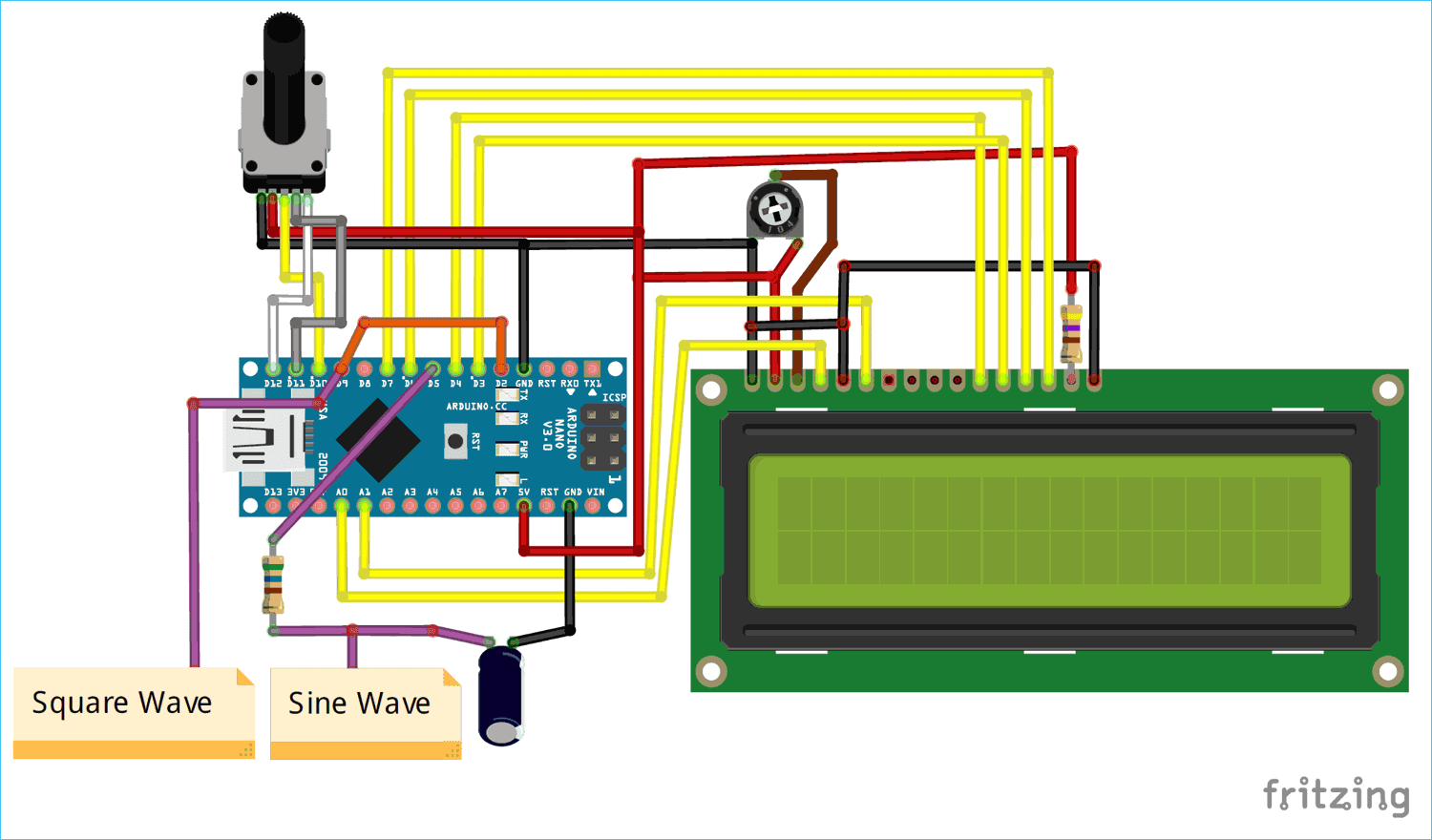
hi friends in this blog lets build a variable frequency generator using arduino
the main feature of this genarator is you can see the output frequency in lcd screen and also you can convert its output to triangular wave or sine by adding rc integrator circuit.the maximum frequency of this genarator is 2mhz
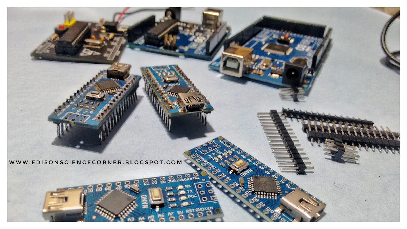
Materials Required
Arduino Nano
16*2 Alphanumeric LCD display
Rotary Encoder
Resistor(4.7K,220ohm)
Perf board


the main feature of this genarator is you can see the output frequency in lcd screen and also you can convert its output to triangular wave or sine by adding rc integrator circuit.the maximum frequency of this genarator is 2mhz
Materials Required
Arduino Nano
16*2 Alphanumeric LCD display
Rotary Encoder
Resistor(4.7K,220ohm)
Perf board

Circuit diagram
Completed circuit on pcb


Thursday, 28 February 2019
HOME AUTOMATION USING ANDROID APP

in this blog i am going to show to how to control home appliences via android app aka home automation
with the help of remotexy.com i created my custom application
if you want make similar then watch my video
U NEED
HC-05 BLUETOOTH MODULE

ARDUINO NANO

RELAY MODULE


circuit diagram

CONNECT VCC TO 5V
GND TO GND
RX T0 D3
TX TO D2
connect the output arduino to relay

this is my homemade relay module.
you can make similar with this circuit diagram

download remotexy android app from playstore .pair with bluetooth module
PASSWORD=1234

you can download circuits,program from here
NOW WE ARE PLAYING WITH HIGH VOLTAGE SO CAREFULL
Subscribe to:
Posts (Atom)