Showing posts with label led. Show all posts

Friday 31 July 2020

NEOPIXEL RGB LED MATRIX

In this tutorial I am going to show you how to build a 5*5 RGB LEDMATRIX USING NEOPIXEL. With this matrix  we can display  mesmarizing animations,  emojis and letters supersimple very attractive. lets gets started!

 Features
  • Very small
  • Millions of colours
  •  Only one wire needed for programming
Materials needed
  • 25*neopixel leds (WS2812 5050smd)
  • Arduino (any arduino)
  • 3D printed jig (you can download .stl)
  • Wires
ABOUT 5050 WS2812B LEDS
Each ws2812 led has 4 pins
  1. Vcc (connects to 5v)
  2. Gnd
  3. Din (connects to arduino)
  4. DO (data out  connects to the next leds in data in)

I don't have indidual ws2812b Leds so i decided to took from ledstrip.for that i heated up the strip with soldering iron (watch video for details)
After gathering all  things  lets start the built
First place neopixel leds in 5*5 matrix jig.Remember place every leds in same Direction
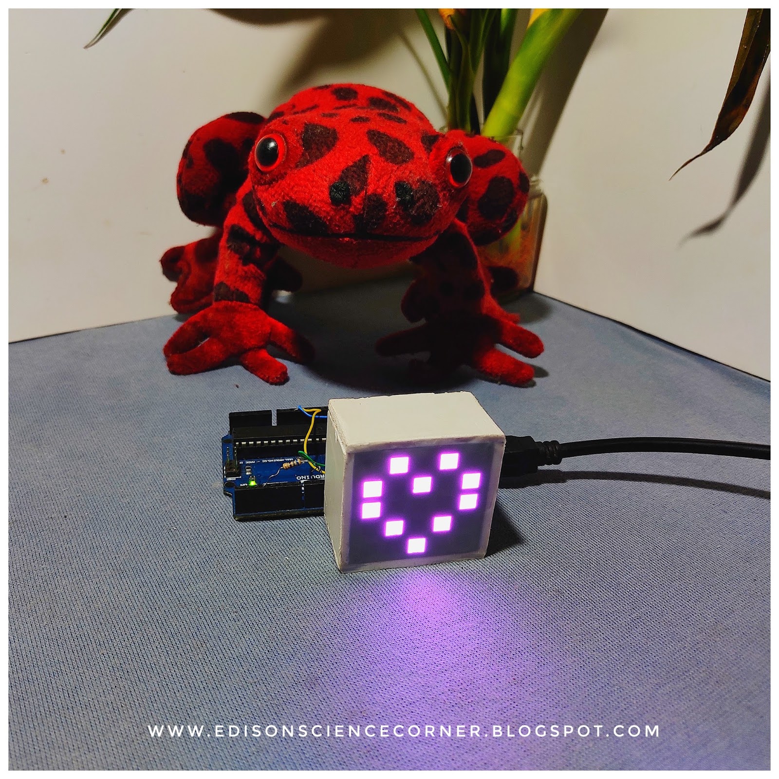
After placing all leds on jig first connect every ground pins of each leds in a row. Then connect VCC of all leds of a row. Do the same for remaining rows. After  finishing thats connect data out of first led to the data in of next led. Data out of each rows connect to next rows first leds. Repeat this for all leds. After finishing everything connect all rows vcc together also ground. Finally connect  wires to common gnd, vcc, data in. Next i made a small enclosure  with foam sheet. And placed the matrix inside the foam case. 
Connections to arduino
Vcc to 5v
Gnd to gnd
Din to D7 (any digital pin)
Thats all about hardware connections

REST IS IN  PROGRAMMING

first install fast led library

After uploading code to arduino should use a 1.5 ampere power supply
Because at  maximum brightness  a neopixel led draws around 60 mA current .we have total 25 leds so 25*60=1.5A

Future plans
  •  Planing to make a easy software to generate code
  •  Bluetooth connectivity and controlling 

Friday 10 April 2020

electronic chameleon

hey..all of you know about the chameleons.yeay they have a special character to change their colour according to with the environments biologically this is known as mimicry. they use this ability to escape from predators and also to capture their prey.
so in this tutorial, I am replicate that ability electronically with the help of Arduino and colour sensor
please watch the making and working video first
now lets start


HOW ITS WORKS

with the help of tcs230 sensor we can read the reflected colour values of a surface  with that data we can control an RGB led 

components needed for this project


connections


Color Sensor      Arduino
-----------      --------
 VCC               5V
 GND             GND
 s0                     8
 s1                     9
 s2                    12
 s3                    11
 OUT                10
 OE                GND

 s0 = 8
 s1 = 9
 s2 = 12
s3= 11
greenLed = 3
blueLed  = 4
red Led  = d2

download code

 chameleon body
.stl

Friday 28 September 2018

how to make rgb led cube


How to Make Rgb Led Cube


in this instructable i am going to make a rgb led cube(charlieplex cube)
ok...what is charlieplex cube...?
Charlieplexing is a technique for driving a multiplexed display in which relatively few I/O pins on a microcontroller are used e.g. to drive an array of LEDs.
The method uses the tri-state logic capabilities of microcontrollers in order to gain efficiency over traditional multiplexing. Although it is more efficient in its use of I/O, there are issues that cause it to be more complicated to design and render it impractical for larger displays. These issues include duty cycle, current requirements and the forward voltages of the LEDs.why charlie cube is differ from other cubes......?
Other cubes use shift registers, decade counters, or other components to control all the LEDs and that will increse the making cost. The charliecube can be run using only 16 digital pinsof arduino with no extra components...total cost this cube is around 9$.


Step 1: Things Need to Make Rgb Led Cube

Picture of Things Need to Make Rgb Led Cube

Step 2: Preparing Leds for Soldering

Picture of Preparing Leds for Soldering
watch video

Step 3: Connections

Picture of Connections
2 More Images

Step 5: Happy Making

Picture of Happy Making

Saturday 25 August 2018

HOW TO MAKE 4*4*4 LED CUBE

An LED Cube is a group of LED's that arranged in a cube shape that can perform some interesting lighting effects according to your program.
in this tutorial i am showing to u how to make  a 4*4*4 led cube
 this cube is controlled by a single atmega chip(arduino nano) that is i am not using any shift registers or any other ics
so lets make it
materials that u need to make cube
3.100ohm resistorshttps://amzn.to/2wdat2a
4.female headerpinshttps://amzn.to/2wp9mvo
5.lead https://amzn.to/2o9q4Ly
diffusing leds
diffuse them by rubbing their glass top with sandpaper.


u can clearly seen that difference
making the jig 
For this , you will need a thick cardboard or wood . Drill 5mm holes into it so that it forms a 4×4 cube pattern with equal distances between all holes.

preparing leds for soldering
the short leg of an LED is its Cathode (-ive pin) and the long leg is Anode (+ive pin). 
Now, using  pliers bend the cathode (short leg) at 90digree angle to the right and then again bend it upwards to make the shape as shown in the image below.

test all leds with multimeter before soldering
CIRCUIT DIAGRAM
circuit diagram
now lets start soldering
first put 4 leds in a row and solder positive leads(common positive)
repeat same for all four rows

connect this rows with single stranded wire
repeat same for 4 layers

now lets start the assembling of cube layers
place and solder first layer to common pcb


repeat same for all layers connect same negative pins to the next corresponding negative pins
connect cathode pins to corresponding arduino pins


LAYER 1 CONNECT TO ARDUINO PIN A0
LAYER 2 CONNECT TO ARDUINO PIN A1
LAYER 3 CONNECT TO ARDUINO PIN A2
LAYER 4 CONNECT TO ARDUINO PIN A3
COLUMN 1 TO ARDUINO PIN A4
COLUMN 2 TO ARDUINO PIN A5
COLUMN 3 TO ARDUINO PIN D0
COLUMN 4 TO ARDUINO PIN D1
COLUMN 5 TO ARDUINO PIN D2
COLUMN 6 TO ARDUINO PIN D3
COLUMN 7 TO ARDUINO PIN D4
COLUMN 8 TO ARDUINO PIN D5
COLUMN 9 TO ARDUINO PIN D6
COLUMN 10 TO ARDUINO PIN D7
COLUMN 11 TO ARDUINO PIN D8
COLUMN 12 TO ARDUINO PIN D9
COLUMN 13 TO ARDUINO PIN D10
COLUMN 14 TO ARDUINO PIN D11
COLUMN 15 TO ARDUINO PIN D12
COLUMN 16TO ARDUINO PIN D13
final look

happy making