Showing posts with label arduinoprojects. Show all posts

Tuesday 15 September 2020

ATMEGA ROBOTIC PCB


Features
 We can make different  robots with this pcb without using any extra chases
  • Line follower
  • Obstacle avoider
  • Android controlled
 We can use pcb as a custom arduino


you can directly print these PCBs from seeedstudio 

Seeed Studio Fusion PCB  service takes care of the entire fabrication process from PCB manufacturing,  parts sourcing, assembly and testing services, so you can be sure that they are getting a quality product. After gauging market interest and verifying a working prototype, Seeed Propagate Service can help you bring the product to market with professional guidance and a strong network of connections.


Friday 31 July 2020

NEOPIXEL RGB LED MATRIX

In this tutorial I am going to show you how to build a 5*5 RGB LEDMATRIX USING NEOPIXEL. With this matrix  we can display  mesmarizing animations,  emojis and letters supersimple very attractive. lets gets started!

 Features
  • Very small
  • Millions of colours
  •  Only one wire needed for programming
Materials needed
  • 25*neopixel leds (WS2812 5050smd)
  • Arduino (any arduino)
  • 3D printed jig (you can download .stl)
  • Wires
ABOUT 5050 WS2812B LEDS
Each ws2812 led has 4 pins
  1. Vcc (connects to 5v)
  2. Gnd
  3. Din (connects to arduino)
  4. DO (data out  connects to the next leds in data in)

I don't have indidual ws2812b Leds so i decided to took from ledstrip.for that i heated up the strip with soldering iron (watch video for details)
After gathering all  things  lets start the built
First place neopixel leds in 5*5 matrix jig.Remember place every leds in same Direction
After placing all leds on jig first connect every ground pins of each leds in a row. Then connect VCC of all leds of a row. Do the same for remaining rows. After  finishing thats connect data out of first led to the data in of next led. Data out of each rows connect to next rows first leds. Repeat this for all leds. After finishing everything connect all rows vcc together also ground. Finally connect  wires to common gnd, vcc, data in. Next i made a small enclosure  with foam sheet. And placed the matrix inside the foam case. 
Connections to arduino
Vcc to 5v
Gnd to gnd
Din to D7 (any digital pin)
Thats all about hardware connections

REST IS IN  PROGRAMMING

first install fast led library

After uploading code to arduino should use a 1.5 ampere power supply
Because at  maximum brightness  a neopixel led draws around 60 mA current .we have total 25 leds so 25*60=1.5A

Future plans
  •  Planing to make a easy software to generate code
  •  Bluetooth connectivity and controlling 

Saturday 11 July 2020

How to CONTROL NEOPIXEL with ARDUINO


In this tutorial i will you how to control individually addressable RGB LEDs or a WS2812B LED strip using Arduino
Hardware needed
1.Arduino

From AliExpress-https://s.click.aliexpress.com/e/_dW8QEj5
From Amazon
https://amzn.to/2Wb3kfD

2.WS2812 rgb leds 


From AliExpress-
https://s.click.aliexpress.com/e/_dSwtVaP
From Amazon-
https://amzn.to/2W9uGTi
3.5volt 3A power supply
From AliExpress-
https://s.click.aliexpress.com/e/_dYjWKsf
From Amazon-
https://amzn.to/2Zk2AH0

WS2812 NeoPixel LED Strip Working

WS2812 LED strips are addressable and programmable Flexible LED strips which are very useful in creating the custom lighting effects. These LED Strips are powered by a 5050 RGB LED with a WS2812 LED driver inbuilt within it. Each LED consumes 60mA current and can be powered from a 5V DC supply. It has a single input data pin which can be fed from the digital pins of Microcontrollers.


 Depending on the intensity of the three individual Red, Green, and Blue LEDs we can create any color we want.


  1. 16.8 million colors per pixel
  2. Single-wire digital control
  3. Operating Voltage: 5V DC
  4. Current Requirement: 60mA per LED
  5. Flexible LED structure
  6. 5050 RGB LED with WS2812 driver

Circuit diagram

Connections
5v to supply 5v
Common Ground to  arduino and led
Datain  to any adigital pin

Install the fastled library
After downloading fastled library from the below link  
Open Arduino IDE and do the following:
Click on "Sketch" and then click "Include library"
Click on "add .zip library"


Programming the LED

#include
 // header file
#define NUM_LEDS 60
 // number of led present in your strip
#define DATA_PIN 6 
// digital pin of your arduino

Depending on your led strip type select appropriate void setup function

void setup() 
{

FastLED.addLeds(leds, NUM_LEDS);

}
Watch the video to  know more


Saturday 20 June 2020

ultrasonic obstacle avoider car

In this tutorial, I am making  a custom obstacle avoiding robot 


you can directly print these PCBs from seeedstudio 

Seeed Studio Fusion PCB  service takes care of the entire fabrication process from PCB manufacturing,  parts sourcing, assembly and testing services, so you can be sure that they are getting a quality product. After gauging market interest and verifying a working prototype, Seeed Propagate Service can help you bring the product to market with professional guidance and a strong network of connections.


jumper    https://s.click.aliexpress.com/e/_dSRayV5
n20 motors              http://s.click.aliexpress.com/e/_dUKwfYM
https://amzn.to/3dkLvk7
ultrasonic module  http://s.click.aliexpress.com/e/_d66uQiU
https://amzn.to/2Yl9eMR
n20 motor socket  http://s.click.aliexpress.com/e/_dUJpEXq
https://amzn.to/2V2aqCO
n20 wheels http://s.click.aliexpress.com/e/_dXfpot2
https://amzn.to/2Br2rrG
l293d motor driver http://s.click.aliexpress.com/e/_dVSiYYY
https://amzn.to/2Nekggj
castor wheelhttp://s.click.aliexpress.com/e/_dShodxE
https://amzn.to/3eo9znq
Arduino uno                https://s.click.aliexpress.com/e/_dUb9laZ
https://amzn.to/2V2wFZ2


Thursday 18 June 2020

ultrasonic levitation full tutorial with theory

It is very interesting to see something floating in the air or free space like alien spaceships. that is exactly what an anti-gravity project is about. The object (basically a small piece of paper or thermocol) is placed between two ultrasonic transducers which generate acoustic sound waves. The object floats in the air because of these waves which seem to be of anti-gravity.

in this tutorial, let's discuss the ultrasonic levitation and let's build a levitation machine using Arduino


How Is This Possible

To understand how acoustic levitation works, you first need to know a little about gravity, air and sound. First, gravity is a force that causes objects to attract one another. An enormous object, like the Earth, easily attracts objects that are close to it, like apples hanging from trees. Scientists haven't decided exactly what causes this attraction, but they believe it exists everywhere in the universe.

Second, the air is a fluid that behaves essentially the same way liquids do. Like liquids, air is made of microscopic particles that move in relation to one another. Air also moves like water does -- in fact, some aerodynamic tests take place underwater instead of in the air. The particles in gasses, like the ones that make up air, are simply farther apart and move faster than the particles in liquids.

Third, the sound is a vibration that travels through a medium, like a gas, a liquid or a solid object. if you strike a bell, the bell vibrates in the air. As one side of the bell moves out, it pushes the air molecules next to it, increasing the pressure in that region of the air. This area of higher pressure is a compression. As the side of the bell moves back in, it pulls the molecules apart, creating a lower-pressure region called a rarefaction. Without this movement of molecules, the sound could not travel, which is why there is no sound in a vacuum.

acoustic levitator

A basic acoustic levitator has two main parts -- a transducer, which is a vibrating surface that makes the sound, and a reflector. Often, the transducer and reflector have concave surfaces to help focus the sound. A sound wave travels away from the transducer and bounces off the reflector. Three basic properties of this travelling, reflecting wave help it to suspend objects in midair.

when a sound wave reflects off of a surface, the interaction between its compressions and rarefactions causes interference. Compressions that meet other compressions amplify one another, and compressions that meet rarefactions balance one another out. Sometimes, reflection and interference can combine to create a standing wave. Standing waves appear to shift back and forth or vibrate in segments rather than travel from place to place. This illusion of stillness is what gives standing waves their name.
Standing sound waves have defined nodes, or areas of minimum pressure, and antinodes, or areas of maximum pressure. A standing wave's nodes are at the reason of acoustic levitation.

By placing a reflector the right distance away from a transducer, the acoustic levitator creates a standing wave. When the orientation of the wave is parallel to the pull of gravity, portions of the standing wave have a constant downward pressure and others have constant upward pressure. The nodes have very little pressure.

so we can place small objects there and levitate
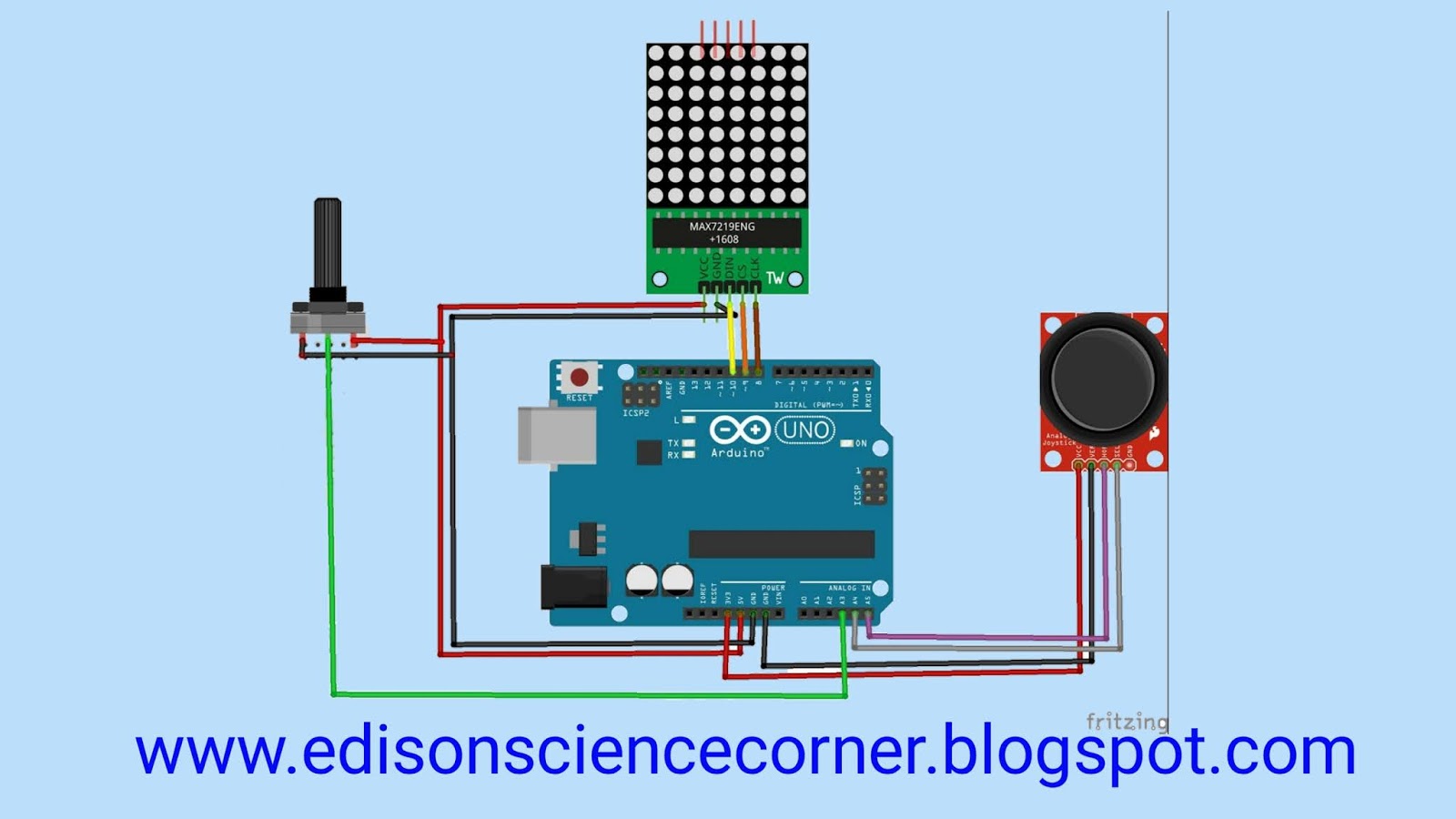
Circuit diagram

the working principle of the circuit is very simple. The main component of this project is an Arduino, L298 motor driving IC, and ultrasonic transducer collected from the ultrasonic sensor module HCSR04. Generally, the ultrasonic sensor transmits an acoustic wave of a frequency signal between 25khz to 50 kHz, and in this project, we are using HCSR04 ultrasonic transducer. This ultrasonic waves makes the standing waves with nodes and antinodes.

this ultrasonic transducer’s working frequency is 40 kHz. So, the purpose of using Arduino and this small piece of code is to generate a 40KHz high-frequency oscillation signal for my ultrasonic sensor or transducer and this pulse is applied to the input of duel motor driver IC L293D (from Arduino A0 & A1 pins) to drive the ultrasonic transducer. Finally, we apply this high-frequency 40KHz oscillation signal along with driving voltage through driving IC (typically 7.4v) on the ultrasonic transducer. As a result of which ultrasonic transducer produces acoustic sound waves. We placed two transducers face to face in the opposite direction in such a manner that some space is left between them. Acoustic sound waves travel between two transducers and allow the object to float.
please watch video for. More information everything explained in that video


Sunday 14 June 2020

How to make temperature sensor using lm35

In this tutorial i am going to make a simple temperature indicator.The main component of this project is a lm35  temperature sensor.And using a max7219  8*8 led matrix  we can indicate the temperature range with emojis in this case i am using 3 different emojis to indicate the temperature range.
For example we can indicate low temperature with smile emoji
Medium temperature with neutral emoji and high temperature with sad emoji.
In this case i am reading my body temperature so that
Smile for temperature <35 div="">
Neutral for temperature between 35-40
Sad for temperature >40
So lets start project

Lm35 
 Features
• Calibrated Directly in Celsius (Centigrade)
• Linear + 10-mV/°C Scale Factor
• 0.5°C Ensured Accuracy (at 25°C)
• Rated for Full −55°C to 150°C Range
• Suitable for Remote Applications
• Low-Cost Due to Wafer-Level Trimming
• Operates From 4 V to 30 V
• Less Than 60-μA Current Drain
• Low Self-Heating, 0.08°C in Still Air
• Non-Linearity Only ±¼°C Typical
• Low-Impedance Output, 0.1 Ω for 1-mA Load

 Description
The LM35 series are precision integrated-circuit temperature devices with an output voltage linearly proportional to the Centigrade temperature. The LM35 device has an advantage over linear temperature sensors calibrated in Kelvin, as the user is not required to subtract a large constant voltage from the output to obtain convenient Centigrade
scaling. The LM35 device does not require any external calibration or trimming to provide typical accuracies of ±¼°C at room temperature and ±¾°C
over a full −55°C to 150°C temperature range. Lower cost is assured by trimming and calibration at the wafer level.The low-output impedance, linear output, and precise inherent calibration of the LM35 device makes interfacing to readout or control circuitry especially easy. The device is used with single power supplies, or with plus and minus supplies. As the
LM35 device draws only 60 μA from the supply, it has very low self-heating of less than 0.1°C in still air. The LM35 device is rated to operate over a −55°C to 150°C temperature range, while the LM35C device is rated for a −40°C to 110°C range (−10° with improved accuracy). The LM35-series devices are
available packaged in hermetic TO transistor packages, while the LM35C, LM35CA, and LM35D devices are available in the plastic TO-92 transistor
package. The LM35D device is available in an 8-lead surface-mount small-outline package and a plastic TO-220 package


8*8 led matrix
MAX7219 IC
The MAX7219/MAX7221 are compact, serial input/out-put common-cathode display drivers that interface microprocessors (µPs) to 7-segment numeric LED displays of up to 8 digits, bar-graph displays, or 64 individual LEDs. Included on-chip are a BCD code-B decoder, multiplex scan circuitry, segment and digit
drivers, and an 8x8 static RAM that stores each digit.Only one external resistor is required to set the segment current for all LEDs. The MAX7221 is compatiblewith SPI, QSPI, and MICROWIRE, and has slewrate-limited segment drivers to reduce EMI.
A convenient 4-wire serial interface connects to all common µPs. Individual digits may be addressed and updated without rewriting the entire display.TheMAX7219/MAX7221 also allow the user to select code-B decoding or no-decode for each digit.
The devices include a 150µA lowpower shutdown mode, analog and digital brightness control, a scan limit register that allows the user to display from 1 to 8 digits, and a test mode that forces all LEDs on.


8*8 led matrix
8×8 matrix consists of 64 dots or pixels. There is a LED for each pixel and these LEDs are connected to total of 16 pins.
As you can see all anodes of same row is connected to one pin and all cathodes of same column are connected to another pin.We have 8 row pins and 8 column pins. If a positive voltage is  applied to R1 pin and negative to C1, we can see that the first pixel turns on. If we apply negative to C2 then the second pixel turns on. Like this we can turn each pixel by hanging the supply pins. However we have 64 supply combinations, and doing it manually is practically impossible. That is why we use max7219 driver and  arduino for interface this matrix
circuit diagram


Monday 8 June 2020

How to control cd stepper motor with Arduino


Components needed
  • A4988 stepper motor driver
  • Arduino
  • Variable resistor
  • Battery
  • Breadboard
  • Jumper wires
https://gist.github.com/EDISON-SCIENCE-CORNER/6797403d10c70c9bb0e9b993f174bc6c

Saturday 30 May 2020

Coffin dance playing by arduino

In this tutorial I am how you can use an Arduino to make music using just with a speaker (no MP3 module required).
First watch this video tutorial


Hardware needed
1.an Arduino
2.A speaker or a buzzer
Circuit diagram

Just connect one wire of the speaker to D8 of the arduino and other end to grond of arduino

How does it work?

The Arduino in this circuit creates tones of different frequencies and plays it through the speaker connected to it. The variation of the frequency of the tone(pitch) with correct timings(rhythm) creates music. The Arduino generates a signal and outputs it through the Digital pin 8. This drives the speaker connected to the pin to create sound.In this tutorial, I have programmed the Arduino to play a song ‘astronomia coffin dance’.

Software side

pitches.h library contains all notes  of all frequencies
With the help of pitches.h i created  this project 
How I made melody[ ] and noteDurations[ ] of this song:

If you take a look at the program, you can find two int arrays: melody[ ] and noteDurations[ ]. The first array contains the notes and the second array contains its corresponding durations. I wrote down the musical notes of this song first and then wrote the melody[ ] array with that.
Then I wrote noteDurations[ ] according to the length of each music note. Here 8 = quarter note, 4 = 8th note, etc. Higher value gives longer duration notes. The note and its corresponding duration is what is there in melody[ ] and noteDurations[ ] respectively. You can modify those and create any song according to your ideas


download code from here

Thursday 28 May 2020

how to read Multiple Analog values Using One Analog Pin

In this tutorial, I am going to show you how to read multiple analog values using only one analog input pin.

why you want to this.

if you are an electronics enthusiast or a hobbyist you might familiar with lots of microcontroller boards like 

  • Arduino Uno
  • Arduino nano
  • Arduino pro mini
  •  esp 8266 nodemcu

Arduino Uno has 6 analog pin , nano has 8 pins, the pro mini has 6 pin

unlike other boards, nodeMCU has only one analog pin so if you want to be read more than one anlog value using nodemcu ?  is it possible to read multiple analog values using only one pin.? yes

how is that possible?

we are  done this by turning on and off sensors like multiplexing .first we turn on one sensor and  we read the analog data from that sensor and at the next step we turn on the next sensor and turnoff the first sensor and read data from the second sensor that it

things needed for this project


  • nodemcu
  • 2*variable resistors
  • 2*diodes
  • breadboard
  • some wires


circuit diagram


in this circuit diagram, you can see I connected positive terminals of variable resistors to digital pin 1 and 2 so we can turn off and on variable resistors by turning on and off the  digital pins

connections

positives of variable resistors to d1 and d2

grounds to grounds

connect analog pins to  diodes positive side

connect  diodes negative end to A0 of nodemcu

I used diodes to overcome overlapping data

that's all about connections


programming


Download library


blynk app setup


Download libraries

simpletimer

blynk

thanks