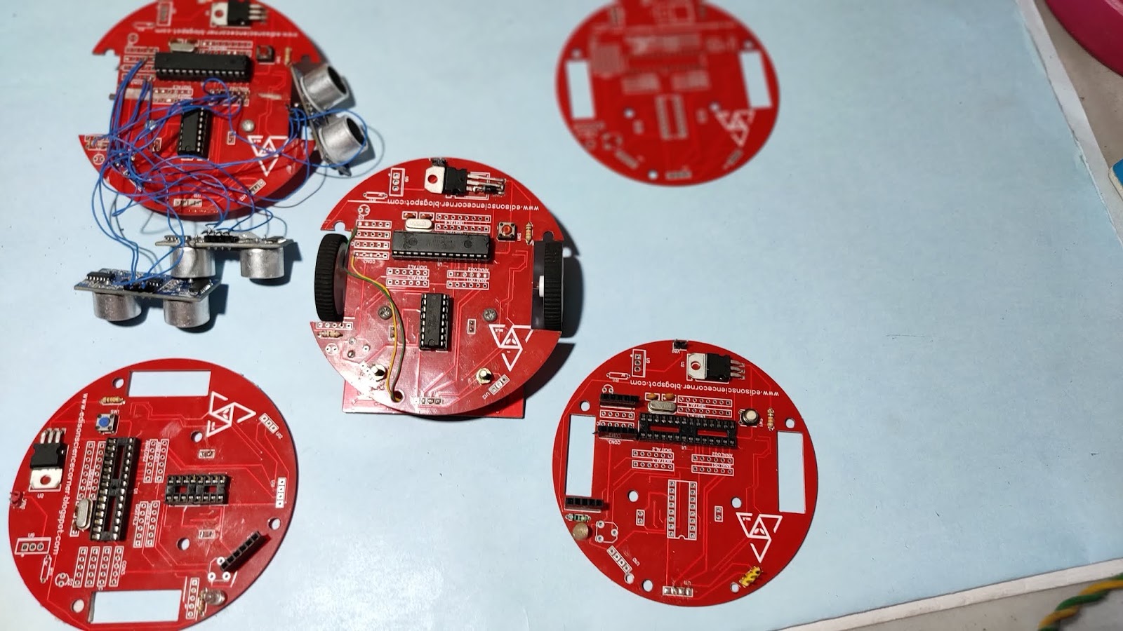
we cant use Arduino board in every project because Arduino is costly and also big size so...In this blog, I am showing how to make your own customized Arduino boardlet's start with a simple circuit
Showing posts with label home. Show all posts
Showing posts with label home. Show all posts
Sunday, 9 January 2022
Friday, 15 May 2020
how to fix broken charging cables at home
in this tutorial, I am going to show you how to fix your broken charging cables at home.
most of the charging cables damaged due to the problem in the USB plug we can solve that by replacing the jack
Wednesday, 13 May 2020
Servo tester using ic 555
in this tutorial, I am going to show you how to make a simple servo tester using 555 ic
components needed
- ic 555
- 10k variable resistor
- 10uf,.1uf capacitors
- 220k,10k,1k resistors
- 1n4148 diodes
working
The principle behind this project is that a 555 timer can be configured in “Astable multivibrator mode” and used to generate the signal for the Servo Motor to work. The servo motors with pulse width modulated signal usually with a frequency of 25-50Hz. The angle of the servo varies according to the ON time period of the signal(i.e, duration of the pulse). Hence, different servos have a different angle of rotation with respect to pulse widths mentioned in there in the datasheet. For example, a pulse of 1 ms, moves the servo towards 0 degrees while a pulse of 2 ms would take it to 180 degrees.
The 555 timer in Astable mode provides an oscillating pulse as output which is switching between high and low states at a certain frequency and pulse width. In Astable Mode the threshold pin and trigger pin of the timer are connected to each other which allows the output to toggle between high and low states. This can be analysed when we look at the internal structure of the 555 containing NPN transistors, and some voltage divider circuits,and flip-flops.
Tuesday, 12 May 2020
tv remote controlled home automation
in this tutorial, I am going to show you how to make simple home automation using tv remote
this circuit uses a TSOP1738 IR receiver module in normal condition, the output pin of the IR module is High, which means the transistor (bd140 PNP) is at logic Low. but when ir signal fall to tsop sensor the output of tsop goes low and transistor will turn on. the output of the transistor is connected to a toggle switch constructed with cd 4017 counter ic
circuit diagram

circuit diagram
componets needed
BC547BTransistor BD1401N40071K resistorCD4017TSOPRELAY100UF capacitor

MOTION DETECTION ALARM
Hello, friends in the tutorial I am going to show you how to make a motion detection alarm. the main component of this project is the PIR sensor
. 

overview of PIR SENSOR
the main component e of this project is a PIR sensor. PIR stands for passive infrared
This module consists of a pyroelectric sensor. As the name & indicates that is pyro means temperature, this sensor produces some energy when it is exposed to heat!
and the term passive means it generates signals without using the energy
it has a lens called fresnel lens and which is used to focus the signal to the sensor.
This module has 3 pins Vcc gnd and out and two potentiometers Right One is used to adjust the output delay time and left one is used to adjust the Sensing range of module
working principle
if a human or heated body comes in front of the sensor. the Sensor will detect movement because the heated body emits energy in the form of IR radiation and the PIR will capture that
working modes
this module has two modes.
the repeatable and non-repeatable mode .
in the non-repeatable mode when the sensor output is high and it goes low after the delay time is over.
But in repeatable mode. It will keep the output high until the detected Object is in the range
CIRCUIT DIAGRAM

Friday, 8 May 2020
how to make conductive paint at home
Conductive paint is an ink that results in a printed object which conducts electricity. It is typically created by infusing graphite or other conductive materials into ink.
Conductive inks can be a more economical way to lay down a modern conductive traces when compared to traditional industrial standards such as etching copper from copper-plated substrates to form the same conductive traces on relevant substrates, as printing is a purely additive process producing little to no waste streams which then have to be recovered or treated.
Tuesday, 5 May 2020
vu meter using arduino
A volume unit (VU) meter or standard volume indicator (SVI) is a device displaying a representation of the signal level in audio equipment.so in this tutorial lets build a VU meter using Arduino.
things needed for this
- Arduino
- led
- aux cable
- jumper wire
- breadboard
circuit diagram
 |
| add an aux to a0 pin |
connections
connect anodes of less to pin 2-13
connect cathodes together and connect to ground
connect aux cable a0 and ground
SOLDERING ON A DOT PCB
arrange in a round shape and solder
Monday, 27 April 2020
Wednesday, 8 April 2020
T rex runner Game controller
in this tutorial, I am going to show you how to make a google dino game automation
all off you know about the t rex aka dino game of google and it famous as no internet game.
the game is very simple just avoid the obstacles by jumping and its like super Mario run.usually to jump we use space bar manually.that's very old school for me...
so in this tutorial, I am going to show you how to make that in automatic that is an automatic controller.
please watch the making video for more details
first, watch this video
the senor
here we want to detect the obstacle and jump to detect the obstacle I am using an LDR
so how an LDR detect that kind of obstacle?
the resistance of LDR changes according to light that is when
the dark time the LDR resistance is very high and vice-versa. so our obstacle is dark in colour so we can get different analog values . with that value with the help of a controller we trigger a servo.
the dark time the LDR resistance is very high and vice-versa. so our obstacle is dark in colour so we can get different analog values . with that value with the help of a controller we trigger a servo.
servo is used to press the space bar. so that's the working principle
circuit diagram
I am using the analog read function of Arduino and I give conditions for servo triggers
Wednesday, 1 April 2020
Monday, 30 March 2020
HOW TO MAKE A SIMPLE IOT HOME AUTOMATION
Hello folks
In this blog, I am going to show you how to control your home appliances using smartphone aka kinda home automation.
For this, we need only
1. esp8266 aka node MCU
2.2channel 5v relay module
The connection is very simple to Connect ground of esp to the ground of relay
Connect VCC to 3v of esp
Connect in1 to D2
Connect in2 to D4
Sunday, 9 February 2020
HOW TO MAKE CUSTOM ARDUINO
then using easyeda online PCB designer software i added rest switch power supply and attached led to pin 13
https://easyeda.com/
after designing the circuit i converted this circuit to pcb
then I upload gerber files to jlcpcb
Components
- ATmega328p Microcontroller IC
- 28 Pin IC Holder
- 16 MHz Quartz Crystal
- Capacitors – 2 x 22pF, 100nF,
- Resistors – 330Ω, ,10KΩ
- LEDs x 2 (Red and Green)
- Push Button (for Reset)
- 5V Regulator (7805)
you can download gerber and circuit from here
Saturday, 30 November 2019
Subscribe to:
Comments (Atom)


