Wednesday 5 August 2020

TECH NEWS 6 AUG 2020


🌐 Google Pay will support mobile checking accounts starting next year, user will get physical debit cards issued through Google 

🌐 Realme 10W Wireless Charger Launched in India at Rs. 899, 50W and 65W SuperDart Chargers Launching ‘Soon’

🌐 PUBG Mobile Lite marks 1st anniversary with new update; brings Varenga map, new weapons

🌐 Google Pixel 5 5G-ready phone by Google officially announced, set for October launch this year

🌐 Lockdown impact: 2.9 million PCs shipped in just 45 days in Apr-June

🌐 Facebook adds official music videos in new challenge to YouTube

🌐 Amazon India launches new warehouse in Ludhiana

🌐 June records 78% jump in UPI transactions 

🌐 ALTBalaji witnessed growth even before COVID-19 outbreak; subscriptions higher in rural than urban market

🌐 Xiaomi Rumoured to Launch Mi 10 Pro Plus, New Products on August 11 come with spd 865 & 30 optical zoom

🌐 Flipkart Big Saving Days Sale Begins on August 6: Top Deals on iPhone XR, Oppo Reno 2F, More

🌐 GPay does not require RBI nod for facilitating financial transactions: Google tells Delhi HC

🌐 Mozilla Firefox Loses Market Share to Microsoft Edge in July 2020: Report

🌐 Money Heist Season 5 Will Be Its Final Season, Netflix Reveals

🌐 Again Realme said laptops could launch in India soon

Friday 31 July 2020

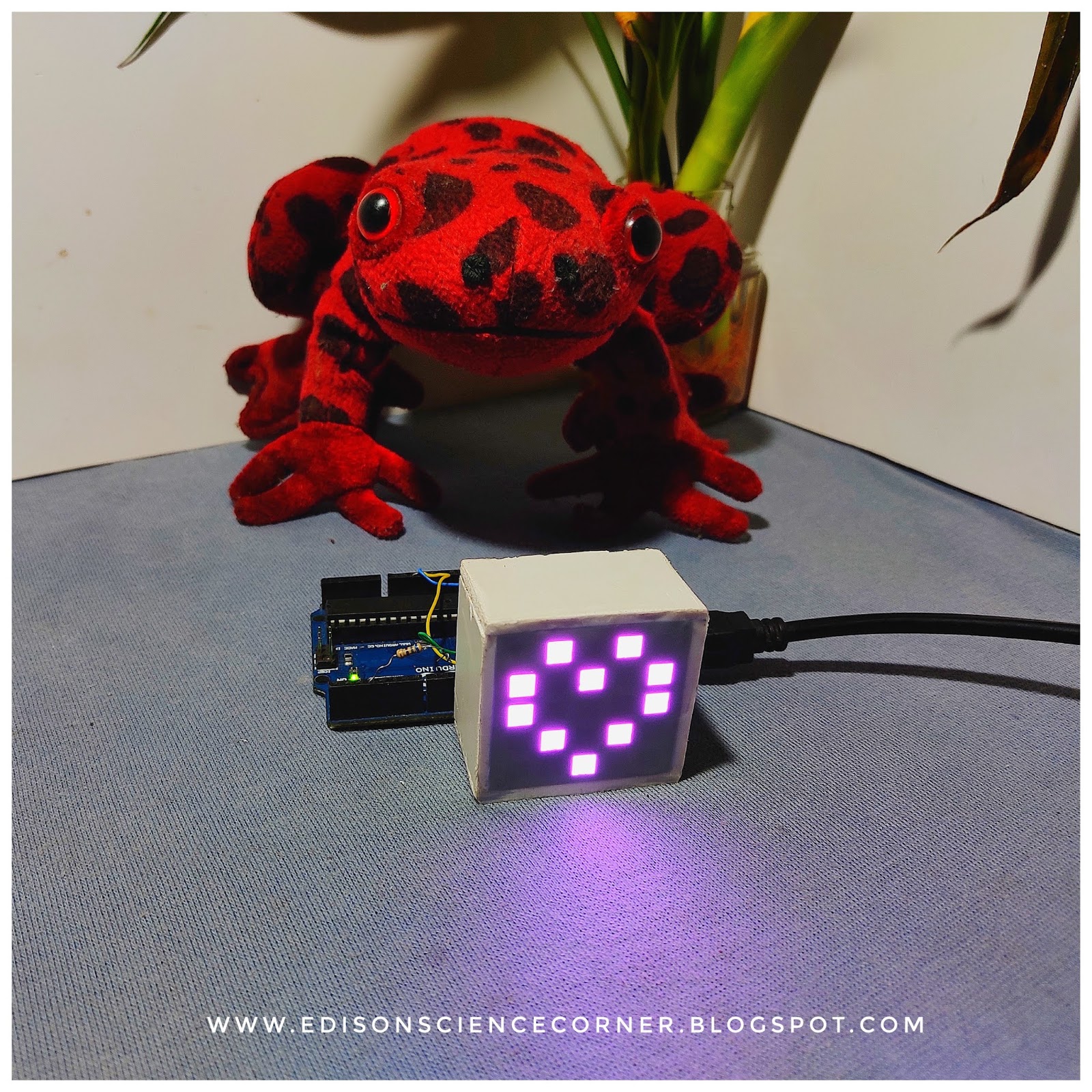
NEOPIXEL RGB LED MATRIX

In this tutorial I am going to show you how to build a 5*5 RGB LEDMATRIX USING NEOPIXEL. With this matrix  we can display  mesmarizing animations,  emojis and letters supersimple very attractive. lets gets started!

 Features
  • Very small
  • Millions of colours
  •  Only one wire needed for programming
Materials needed
  • 25*neopixel leds (WS2812 5050smd)
  • Arduino (any arduino)
  • 3D printed jig (you can download .stl)
  • Wires
ABOUT 5050 WS2812B LEDS
Each ws2812 led has 4 pins
  1. Vcc (connects to 5v)
  2. Gnd
  3. Din (connects to arduino)
  4. DO (data out  connects to the next leds in data in)

I don't have indidual ws2812b Leds so i decided to took from ledstrip.for that i heated up the strip with soldering iron (watch video for details)
After gathering all  things  lets start the built
First place neopixel leds in 5*5 matrix jig.Remember place every leds in same Direction
After placing all leds on jig first connect every ground pins of each leds in a row. Then connect VCC of all leds of a row. Do the same for remaining rows. After  finishing thats connect data out of first led to the data in of next led. Data out of each rows connect to next rows first leds. Repeat this for all leds. After finishing everything connect all rows vcc together also ground. Finally connect  wires to common gnd, vcc, data in. Next i made a small enclosure  with foam sheet. And placed the matrix inside the foam case. 
Connections to arduino
Vcc to 5v
Gnd to gnd
Din to D7 (any digital pin)
Thats all about hardware connections

REST IS IN  PROGRAMMING

first install fast led library

After uploading code to arduino should use a 1.5 ampere power supply
Because at  maximum brightness  a neopixel led draws around 60 mA current .we have total 25 leds so 25*60=1.5A

Future plans
  •  Planing to make a easy software to generate code
  •  Bluetooth connectivity and controlling 

Friday 24 July 2020

DIY mist maker using IC 555


In this video tutorial i am showing how to build a mist/fog maker using IC 555

Components needed
  • Piezoelectric disc
  • Ic NE555
  • 220uH inductor
  • IRF Z44 MOSFET
  • 10nf capacitor
  • 2*100nf capacitors
  • 10ohm resistor
  • 5k variable resistor

The main component of this project is a piezo electric disc the working of the piezo is very simple.Every piezo has its own resonance frequency i n our case that is 113kz. So if we apply 113kz signal With suitable voltage piezo disc will start to vibrate with 113kz frequency. If we place the piezo on top of a water surface the water will also start to vibrate.mist or fog will form due to the high vibration of water+air
(Watch the video for more detaild view)
Circuit diagram
This circuit is created by greatscott
Working of this circuit
  • Here 555 is using for genarating 113khz signal we can adjust that with 5k variable resistor
  • Using the MOSFET we drive piezo with high voltag
  • Should use 15 volt power supply
I soldered everything in a common pcb
Dont dip the piezo disc on water place the disc just above the water surface


Thursday 16 July 2020

Neopixel rainbow VU meter

In this tutorial, I am going to show you how to build A beautiful VU meter using neopixel LEDs.its has 5 different animations, light intensity control and sensitivity control. super easy let's start 

what is VU meter

A volume unit (VU) meter or standard volume indicator (SVI) is a device displaying a representation of the signal level in audio equipment.

hardware needed

  • Arduino (you can use any Arduino )
  • neopixel led (no matter how many)
  • audio socket
  • 2*10k variable resistors(use the high quality to reduce noise)
  • push button switch
  • foam board(or MDF or plywood)

what is neopixel led

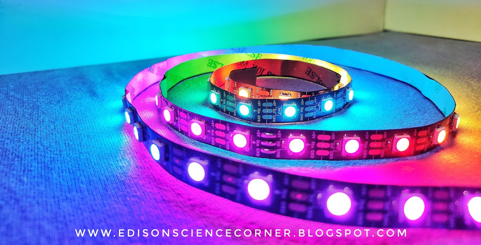
WS2812 LED strips are addressable and programmable Flexible LED strips which are very useful in creating the custom lighting effects. These LED Strips are powered by a 5050 RGB LED with a WS2812 LED driver inbuilt within it. Each LED consumes 60mA current and can be powered from a 5V DC supply. It has a single input data pin which can be fed from the digital pins of Microcontrollers. Depending on the intensity of the three individual Red, Green, and Blue LEDs we can create any colour we want

features of addressable LEDs

  • 16.8 million colours per pixel
  • Single-wire digital control
  • Operating Voltage: 5V DC
  • Current Requirement: 60mA per LED
  • Flexible LED structure
  • 5050 RGB LED with WS2812 driver

circuit diagram


connections

connect ground of led strip to ground 
connect 5volt of the led strip to 5volt of Arduino
data in pin to D6 and D5
connect the variable resistor to A0 and A1
left channel to A4 and right to A5
connect button to D4

making of the led tower

so I am using foam board to support the led stip you can use wood or MDF boards first I placed and fixed the neopixel on foam board then I cut and removed excess part.
then I also made a foam board base
and placed the led tower on top

Saturday 11 July 2020

How to CONTROL NEOPIXEL with ARDUINO


In this tutorial i will you how to control individually addressable RGB LEDs or a WS2812B LED strip using Arduino
Hardware needed
1.Arduino

From AliExpress-https://s.click.aliexpress.com/e/_dW8QEj5
From Amazon
https://amzn.to/2Wb3kfD

2.WS2812 rgb leds 


From AliExpress-
https://s.click.aliexpress.com/e/_dSwtVaP
From Amazon-
https://amzn.to/2W9uGTi
3.5volt 3A power supply
From AliExpress-
https://s.click.aliexpress.com/e/_dYjWKsf
From Amazon-
https://amzn.to/2Zk2AH0

WS2812 NeoPixel LED Strip Working

WS2812 LED strips are addressable and programmable Flexible LED strips which are very useful in creating the custom lighting effects. These LED Strips are powered by a 5050 RGB LED with a WS2812 LED driver inbuilt within it. Each LED consumes 60mA current and can be powered from a 5V DC supply. It has a single input data pin which can be fed from the digital pins of Microcontrollers.


 Depending on the intensity of the three individual Red, Green, and Blue LEDs we can create any color we want.


  1. 16.8 million colors per pixel
  2. Single-wire digital control
  3. Operating Voltage: 5V DC
  4. Current Requirement: 60mA per LED
  5. Flexible LED structure
  6. 5050 RGB LED with WS2812 driver

Circuit diagram

Connections
5v to supply 5v
Common Ground to  arduino and led
Datain  to any adigital pin

Install the fastled library
After downloading fastled library from the below link  
Open Arduino IDE and do the following:
Click on "Sketch" and then click "Include library"
Click on "add .zip library"


Programming the LED

#include
 // header file
#define NUM_LEDS 60
 // number of led present in your strip
#define DATA_PIN 6 
// digital pin of your arduino

Depending on your led strip type select appropriate void setup function

void setup() 
{

FastLED.addLeds(leds, NUM_LEDS);

}
Watch the video to  know more


Thursday 9 July 2020

Tuesday 7 July 2020

GOOGLE ASSISTANT BASED SCROLLING DISPLAY


In this tutorial, I am going to show you how to make Google Assistant based scrolling LED display.that is we can change the scrolling text with the help of google assistant
 So let's start
Please watch the video till the end to get some ideas

Things needed for this

Nodemcu


8*8led matrix


Connections

CLK to D5

CS to D8

DIN to D7 and

Vcc  to Vcc 

GND to GND 


Adafruit io setup

First, go to io.adafruit.com


Then sign up with your Google account


 you will see Welcome Dashboard click on it, 


then click on Create New Block 

and select Text 


then enter LED Matrix And click Create then select  LED Matrix and click Next then Create Block.


After that go back to your dashboard and select View AIO Key and copy that key
Now open the code and paste the io key do the same for username.
Also, give SSID and password there. 
After that upload Sketch to nodemcu

 IFTTT AND  GOOGLE ASSISTANT

First, go to ifttt.com
Sign up with your Google account (the same account that used in adafruit)


After that click on create


Then click on  first + icon and search Google Assistant and select it then click Connect select account and allow it
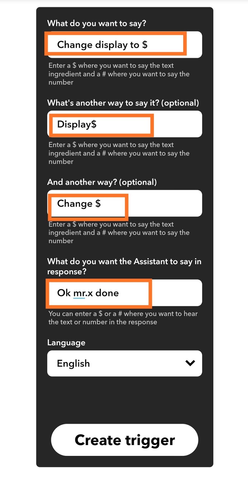
Then select Say a Phrase with Text Ingredient and here type


Then u need to give the trigger commands do it as you wish
 "change matrix to $" so whenever you will say change matrix to and whatever will be after to(i.e in place of $ symbol), will be displayed.
You can select multiple triggers like that. 
Next, select what assistant will reply. 
Then select Create Trigger.

 Now click on the next + icon  and search Adafruit click Connect and authorize it
Then select Send Data to Adafruit IO,
select the feed name which we created earlier then click on Add Ingredient and select Text Field and hit Create Action.
That's all about the software side