
in this tutorial lets explore what is a servo
what is a servo
A servo motor is a rotary actuator or linear actuator that allows for precise control of angular or linear position, velocity and acceleration. It consists of a suitable motor coupled to a sensor for position feedback. It also requires a relatively sophisticated controller, often a dedicated module designed specifically for use with servomotors.Servomotors are not a specific class of motor, although the term servomotor is often used to refer to a motor suitable for use in a closed-loop control system.
Servomotors are used in applications such as robotics, CNC machinery or automated manufacturing.

We are experimenting with sg90 servo
Lets open and inspect what inside a servo

gear system-used to reduce rpm and increase torque
control circuit-kc8801ic based control circuit
variable resistor -used to give feedback
How to control a servo
Servos are controlled by sending an electrical pulse of variable width or pulse width modulation (PWM), through the control wire. There is a minimum pulse, a maximum pulse, and a repetition rate. A servo motor can usually only turn 90° in either direction for a total of 180° movement. The motor's neutral position is defined as the position where the servo has the same amount of potential rotation in both the clockwise or counter-clockwise direction. The PWM sent to the motor determines the position of the shaft, and based on the duration of the pulse sent via the control wire; the rotor will turn to the desired position. The servo motor expects to see a pulse every 20 milliseconds (ms) and the length of the pulse will determine how far the motor turns. For example, a 1.5ms pulse will make the motor turn to the 90° position. Shorter than 1.5ms moves it in the counter-clockwise direction toward the 0° position, and any longer than 1.5ms will turn the servo in a clockwise direction toward the 180° position
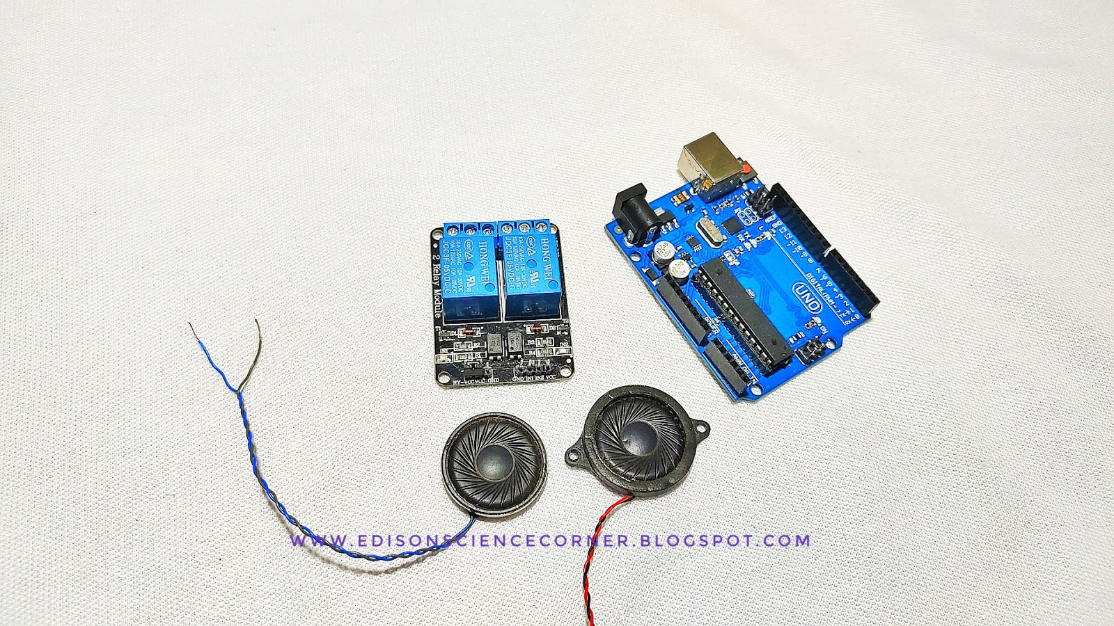
components needed
- servo
- Arduino
- variable resistor
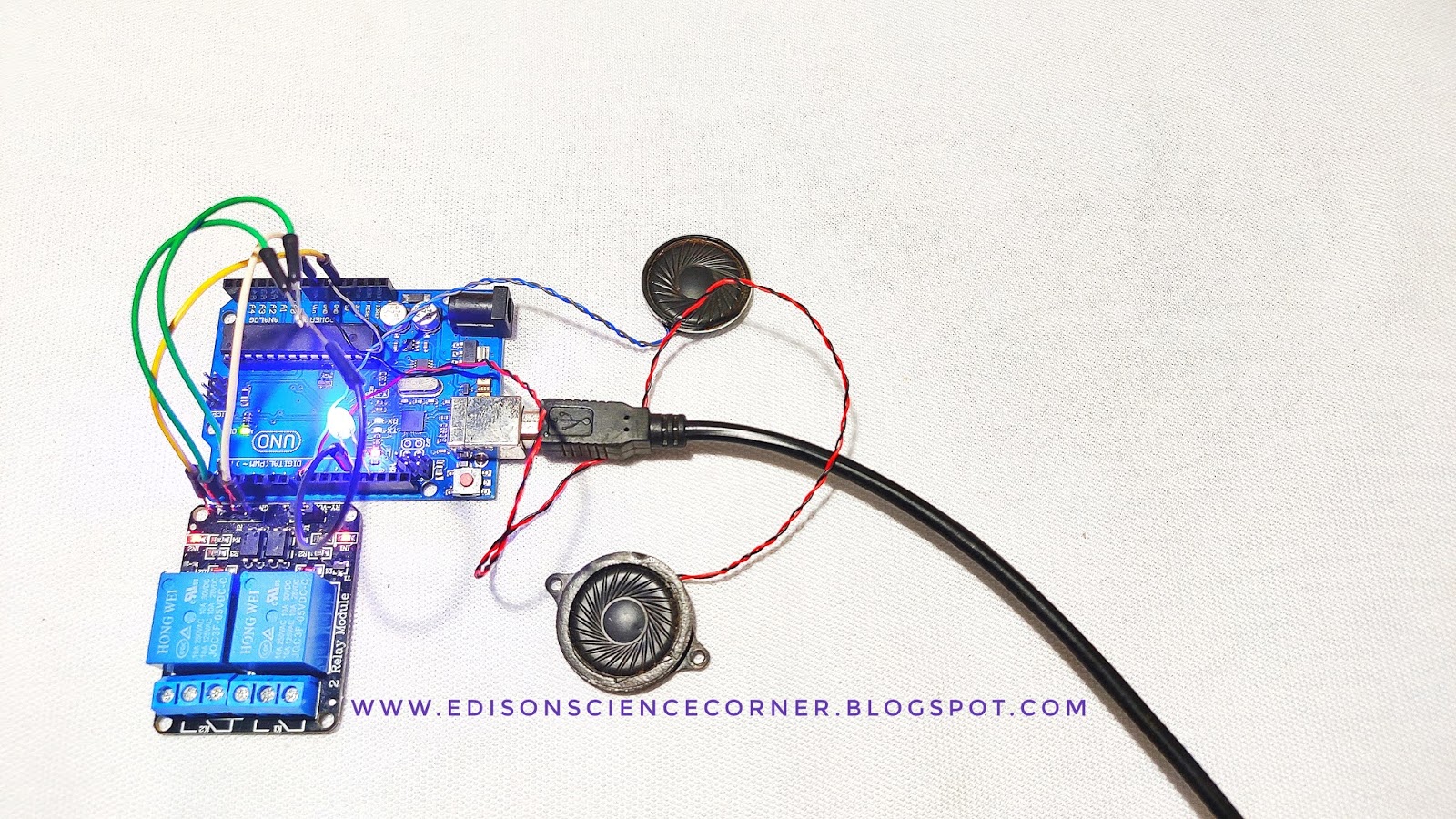
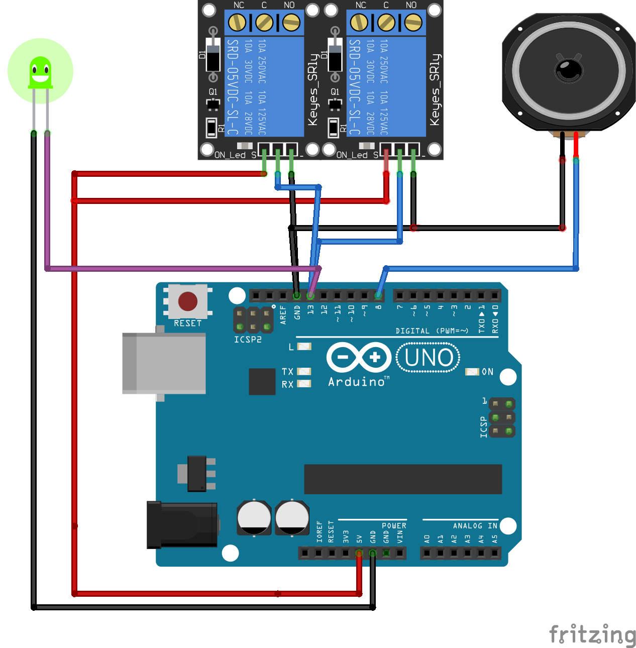
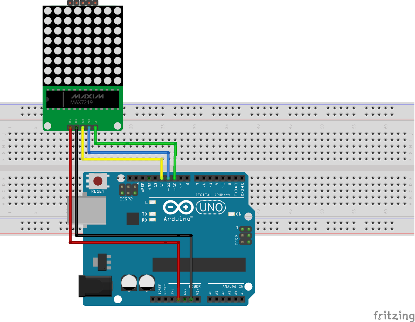
circuit diagram

a servo has 3 pins
connections with Arduino
connect VCC to 5v (red)
connect gnd to gnd(brown)
signal wire to D9 (orange)

after downloading install library
then open example sketch ( download from here ) and upload that's all


