In this blog i am going to show you how to build your own beautiful arduino clock
watch video


for this you will need following things
1) 54 LEDs. or 4 seven segment display

2) 12* 1n4148 diodes
3) 3 *470 ohm resistors
4) DS1307 real time clock IC.


6) Prefboard
7) ATMega328 with arduino bootloader.
8)16MHz crystal.
9) two 22pF caps.
10) 28 pin IC socket for the ATMega328.

11)10 k resistors
12)acrylic sheet
basics
The circuit uses the ATmega328p micro controller (the same as the Arduino uno board) and the DS1307 clock IC. You can easily set/change the time by pressing the setup buttons. It can be powered on with USB cable from your computer
circuit diagram
 TESTING WITH SEVEN SEGMENT DISPLAY ON BREADBORD
FRITZING IMAGE


NOW ITS TIME TO BUILD CUSTUM BUID MATRIX DISPLAY
first we need leds u can use any kind leds. i prefer milky ones
how to turn ordinary leds to milky leds
 using a sandpapper we can easily turn normal led to milky ones
 do this for all leds
SEE THE DIFFERENCE


 NOW LETS CREATE CLOCKS FRONT PANEL
for this we need a led frame so i created a 3d model
 this print is done by eazyfab.com
you can print ur designs ineazyfab
you download this from here front panel
now lets make led display

arrange 3 leds as row and 5 leds for column follow the picture
 black dot represent the corresponing leds of 7 segment display
connect all anodes together(common anode)


watch video


for this you will need following things
1) 54 LEDs. or 4 seven segment display

2) 12* 1n4148 diodes
3) 3 *470 ohm resistors
4) DS1307 real time clock IC.


6) Prefboard
7) ATMega328 with arduino bootloader.
8)16MHz crystal.
9) two 22pF caps.
10) 28 pin IC socket for the ATMega328.

11)10 k resistors
12)acrylic sheet
basics
The circuit uses the ATmega328p micro controller (the same as the Arduino uno board) and the DS1307 clock IC. You can easily set/change the time by pressing the setup buttons. It can be powered on with USB cable from your computer
circuit diagram

FRITZING IMAGE


NOW ITS TIME TO BUILD CUSTUM BUID MATRIX DISPLAY
first we need leds u can use any kind leds. i prefer milky ones
how to turn ordinary leds to milky leds


SEE THE DIFFERENCE


for this we need a led frame so i created a 3d model

you can print ur designs ineazyfab
you download this from here front panel
now lets make led display


connect all anodes together(common anode)

all didodes are 1n4148
CONNECT LED 1,2,3 TOGETHER.
CONNECT LED A AND 1 WITH 2 DIODES THEN CONNECT TO DIGITAL PIN 2 . LED B AND 3 CONNECT TO DP 3.
LED C AND 4 CONNECT DIRECTLY AND THEN CONNECT DP 4 WITH 470 OHM RESISTOR .
LED D CONNECT DP 5 WITH 470 OHM RESISTOR.
LED 5 AND E CONNECT TO DP 12.
LED F AND 6 CONNECT TO DP 7 .
LED G AND 5 CONECT TO DP 8.
COMMON ANODE CONNECT TO DP PIN 6 .
so this is the first digit of our clock for 2,3,4 digit connect each and every led corresponds to no. and letter follow the circuit diagram


to save some space we use standalone arduino circuit


now its time to soldering


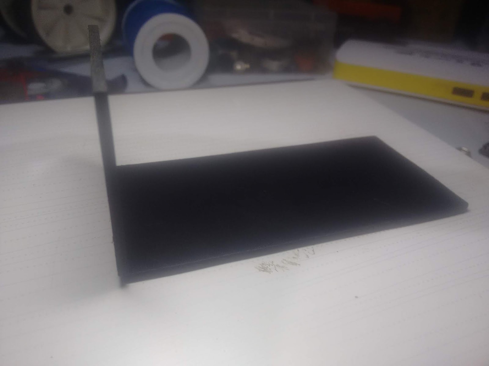
now lets make the case
from black acrylic sheet i created the case and for front i used a a semitransperant sheet


finished


final look
arduino codeclock
happy making i will update more info soon .thanks

No comments:
Post a Comment